

Devices
LoDi-Hobby-M
News & updates
The decoder you want. More possibilities for your Hobby loco.
The LoDi-Hobby-M brings modern decoder technology and new functions to your Märklin® Hobby locomotive or Hobby ICE. The precision-fit motor board replaces the original decoder board and offers a 21MTC interface for a loco or sound decoder of your choice. The existing motor is kept.
You decide which decoder suits your wishes and your digital system. Its configuration lets you set up the available lighting and extra functions as you like. Thanks to the plug-in connection, changing the decoder later is easy too.
Up to ten function outputs leave room for extra lighting and other functions. With a suitable sound decoder and speaker you can add sound. Series resistors on all LED outputs make wiring easier; the switchable supply for current-carrying couplings opens up further options for the coach lighting.
Properties of the LoDi-Hobby-M
- 21MTC interface for a loco or sound decoder of your choice
- Up to ten function outputs: eight AUX plus front and rear lights
- Series resistors integrated on all LED outputs
- Switchable supply for current-carrying couplings
- The existing motor is reused
- Speaker connection for a suitable sound decoder
A 21MTC decoder of your choice
Pick a suitable loco or sound decoder and plug it onto the 21-pin MTC interface. Its output assignment and type must match the board. AUX3 and AUX4 can be adapted to amplified or logic outputs with the solder jumpers.
Up to ten function outputs
Eight AUX outputs plus front and rear lights. How many can actually be used depends on the decoder and its configuration.
LED series resistors already fitted
All LED outputs have series resistors installed. That keeps the wiring of the vehicle lighting tidy.
Switching the current-carrying coupling
The coupling supply is switchable. Solder jumpers select centre rail or vehicle ground as the supply.
Reusing the existing motor
In the conversion shown, the motor is unsoldered from the original decoder and moved over to the new LoDi-Hobby-M.
Ready for lighting and sound
In the vehicle shown, connectors take the original lighting strips. A speaker connection is provided for a suitable sound decoder.
Fitting, step by step
The pictures show the conversion of a Hobby loco chassis from the original decoder to the LoDi-Hobby-M. The motor is kept and moved over to the new board.
Useful tools: soldering iron with a fine tip, solder, desoldering aid, a suitable screwdriver and tweezers. Disconnect the vehicle from the power supply during the conversion.
1. Release the lighting strips
After opening the vehicle, first note where the wires and lighting strips run. Then carefully release the strips from the connectors of the original decoder.
2. Remove the decoder and motor
Undo the connected vehicle wires and the fixing screws. Then take out the unit of original decoder and motor. The cardan shafts come free as you do.
3. Unsolder the motor from the original decoder
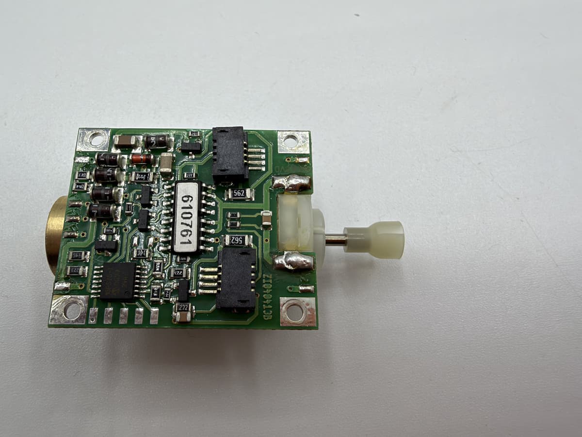
Original decoder with the motor’s two solder joints 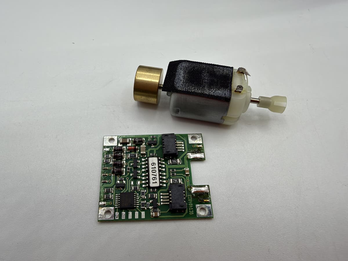
After unsoldering: motor and original decoder apart
The motor is soldered to the original decoder by two tabs. Undo these two solder joints so the motor can be separated from the board.
4. Move the motor to the new board
Line the motor up under the LoDi-Hobby-M. Solder its two tabs to the motor pads provided.
5. Fit the unit into the chassis
Put motor and board back into the chassis. Take up the cardan shafts correctly and fix the board at the mounting points provided.
6. Check position and clearance
The side view shows the position of the motor under the board. Route the wires so that they do not get trapped when reassembling.
7. Connect lighting and power
In the vehicle shown, the original lighting strips are connected to the connectors of the LoDi-Hobby-M. The vehicle supply goes to the solder pads provided.
Finally: decoder and function test
Before plugging in the decoder, set the solder jumpers to match its output type. After checking the wiring and solder joints, plug a 21MTC decoder that suits the board on in the right orientation. Then test the motor, direction, lighting and any extra functions. Check the clearance before closing the body.
Suitable vehicles
The LoDi-Hobby-M fits the following Märklin® Hobby locomotives and the Hobby ICE 2, including many variants of the class 185, class 146, Re 482 and the Hercules family. For starter sets and train packs, compatibility refers to the Hobby locomotive included.
| Märklin item | Vehicle |
|---|---|
| 36837 | Superman set – class 185 and Hercules / series 2016 |
| 36850, 36851, 36852, 36853, 36854, 36855, 36856, 36858 | Hobby electric locos class 185 / Re 482 and variants |
| 36830, 36831, 36832, 36833, 36834, 36835, 36836 | More Hobby electric locos of the class 185 / 146 family |
| 29130, 29135, 29470, 29475, 29480, 26533, 26553 | Starter sets and train packs with class 185 / 146 / Re 482 |
| 36790, 36791, 36792, 36794, 36845, 36846, 36847, 36848, 36849 | Hercules / ER20 and series 2016 |
| 36602, 36606, 36608, 36611, 36612, 36614, 36621, 36895 | More Hobby locomotives |
| 36600, 36601, 36603, 26538, 29478, 29350 | More loco and pack variants |
| 36711 | Hobby ICE 2 |
Connection overview
The labelled board view shows the connections for motor, decoder, lighting, speaker and current-carrying coupling. The numbers on the photo belong to the legend below the board.
Lighting and extra functions
All LED outputs already have series resistors. Vcc is the common positive for the lighting. F0F and F0R are for the front and rear lights; R0F and R0R for the red lights. The AUX connections labelled on the board are there for extra functions.
Which outputs and functions are available depends on the pin assignment and configuration of the decoder used. For the track connections, keep the centre-rail and ground assignment of the original wiring.
Setting the solder jumpers
SJ1 to SJ4 adapt AUX3 and AUX4 to your decoder’s output type. SJ5 and SJ6 decide whether the switchable coupling supply carries centre rail or vehicle ground.
As delivered: all six solder jumpers are open. An open jumper has no connection between its two pads. To close it, join the pads with a little solder. Only change jumpers with the vehicle disconnected.
AUX3 and AUX4: amplified or logic?
An amplified decoder output can switch the load directly. A logic output only supplies a control signal and needs the transistor on the LoDi-Hobby-M for that. You will find the output type in the decoder maker’s manual.
| Output | Decoder output type | Solder jumpers |
|---|---|---|
| AUX3 | Amplified output – the decoder switches the load directly | SJ1 closed, SJ3 open |
| AUX3 | Logic output – the board transistor switches the load | SJ3 closed, SJ1 open |
| AUX4 | Amplified output – the decoder switches the load directly | SJ2 closed, SJ4 open |
| AUX4 | Logic output – the board transistor switches the load | SJ4 closed, SJ2 open |
Supply for the current-carrying coupling
Choose the supply to suit the connected coach lighting. The coupling output may be loaded with at most 1 A.
| Supply wanted | Closed jumper | Open jumper |
|---|---|---|
| Vehicle ground | SJ5 | SJ6 |
| Centre rail | SJ6 | SJ5 |
Technical data
| Property | Value |
|---|---|
| Product | LoDi-Hobby-M |
| Board version | V3 |
| Outer dimensions (length × maximum width) | 100.5 × 29.5 mm |
| Width at the ends | 23.5 mm |
| Board thickness without components | 1.5 mm |
| Height at the highest point with decoder | Approx. 13 mm as a guide; depends on the decoder |
| Decoder interface | 21-pin MTC |
| Function outputs | Up to 10: 8 AUX + front/rear lights |
| Operation | Digital |
| Maximum track voltage | 22 V |
| Maximum current at the track input | 3 A |
| Coupling output | Max. 1 A |
| AUX outputs with transistor amplification | Max. 100 mA per output |
| Adapting AUX3 and AUX4 | Amplified or logic output by solder jumper |
| LED outputs | With integrated series resistors |
| Coupling supply | Switchable; centre rail or ground by solder jumper |
| Motor | Existing motor is reused |
| Sound | Speaker connection provided |
| Solder jumpers as delivered | SJ1 to SJ6 open |
| Motor and direct decoder outputs | Rating as specified by the decoder maker |
Dimensions for fitting
The board is 100.5 mm long. In the middle it is at most 29.5 mm wide, 23.5 mm at both ends. The outline drawing shows the dimensions and the position of the cut-outs.
The height of approx. 13 mm at the highest point is a guide value with decoder. The actual height depends on the decoder chosen, so check the clearance in the vehicle with the decoder you intend to use.
Mind the decoder’s ratings
The 3 A figure is the maximum current at the board’s track input. The permissible load on the motor connection and on outputs switched directly by the decoder depends on the decoder used.
AUX outputs switched through the board transistors may each be loaded with at most 100 mA. Observe the pin assignment, output type and limits in the decoder maker’s manual and the solder jumper settings above. The digital protocols and functions available are determined by the decoder used.
Questions about the conversion?
Not sure about your vehicle? Tell us the item number and the existing drive – by email to info@lokstoredigital.de. Experienced users also help in the LoDi forum.
Märklin® is a trademark of Gebr. Märklin & Cie. GmbH.